Frequency Converter

Static (solid state) frequency converters convert AC electrical power of one frequency into AC electrical power of another frequency. To realize high efficiency, great manageability and energy saving in industrial induction motor related applications, it is necessary to adopt controllable frequency converter systems.

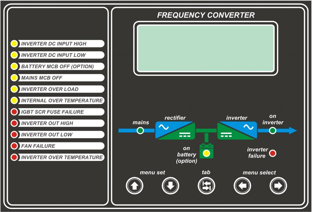
The power conversion process isolates the critical load from the normal mains disturbances and isolates the mains from load induced reflected harmonics affecting other loads connected to the input mains feeder. The rectifier converts AC power into DC to provide the necessary DC for continuously rated capacity of the inverter. IGBT semiconductor modules are used in PWM inverter and the control logic creates the precise sinusoidal output waveform with a very low harmonic content. Thyristor semiconductor modules are also used in rectifier for reliable operation.

The system consists of rectifier, inverter, output isolation transforme, controls and monitoring. The AC output of the inverter is connected to the critical load,

  • Microprocessor Based Control
  • Low Noise Level with 16 kHz Switching Frequency
  • Controlled DC Bus which be able to connect batteries
  • High reliability in Non Linear Loads with 6 module IGBT
  • High Frequency Switching IGBT İnverter
  • Full Bridge Thyristor Module Rectifier
  • Pure Sine Wave Shape
  • LCD Screen
  • Low Noise Level with Smart Fan System
  • Online Double Conversion System
  • Crest Factor bigger than 3:1
  • Galvanic Output Isolation Transformer
  • Input Harmonic Filter
  • %15 Input Voltage Tolerance
  • %5 Input Frequency Tolerance
  • Over Voltage, Over Load, Short Circuit, Over Heat Electronic Protection
  • RS485 Communication Equipment
  • MODBUS Based Communication Option on Network
  • Computer User Interface
  • Remote Monitoring, Parameter Setting and Backward Event Log Memory
GENERAL
Model FK Series
Topology Double Conversion Online System
Control Microprocessor Controlled System
RECTIFIER
TopologyFull Bridge Phase Angle Controlled Thyristor Module Rectifier
Control Microprocessor Controlled System
Nominal Input Voltage 110 VAC / 220 VAC / 230 VAC / 240 VAC / 380 VAC / 400 VAC / 415 VAC / 480 VAC ±15%
Nominal Input Frequency50 hz. ±5% or 60 hz. ±5%
Input Cosφ≥ 0.8 Inductive
Nominal DC Voltage110 VDC / 125 VDC / 144 VDC / 220 VDC / 264 VDC / 360 VDC
Static Tolerance <1%
Output Voltage Ripple RMS<1% (at full load)
ProtectionsThermic‐Magnetic Over Current Protection, Over Voltage Protection, EMI‐RFI Filter
INVERTER
Topology3 Full Bridge 6 high Frequency IGBT Inverter Modules (3 Phase); 1 Full Bridge 2 high Frequency IGBT Inverter Modules (1 Phase)
Isolation TransformerGalvanically Isolated (standard)
Power Factor 0.8
Nominal Input Voltage 110 VDC / 125 VDC / 144 VDC / 220 VDC / 264 VDC / 360 VDC +/-15%
Nominal Output Voltage110 VAC / 220 VAC / 230 VAC / 240 VAC / 380 VAC / 400 VAC / 415 VAC / 480 VAC
Voltage Tolerance
static± 1%
dynamic with 100% load change± 10% in 50 msec.
Overload
at 125% Load10 minutes
at 150% Load1 minute
Waveform Pure Sinusoidal
Total harmonic Distortion (ThDv)
at Linear Load< 3%
at Non-Linear Load< 8%
Crest Factor 3 : 1 (at full load)
Nominal Output Frequency50Hz or 60Hz
Short-circuit behaviour: 3 x Nominal Output Current
Protection Short Circuit, Over Current, Over Voltage and Over Heat Electronic Protection
LCD FRONT PANEL
Indicators and Buttons2 x 16 LCD Panel, Menu Selection and Parameter Setting Buttons
Warning MessagesInput Fuse/DC Voltage High‐Low /Over Load/Device Over Heat/Inverter Over Heat /Inverter SCR Fuse/Output Low‐High
MonitoringOutput Voltage/Output Frequency/Inverter Load Percentage/DC Bus Voltage/ Device Temperature / Event History
Adjustable ParametersDC Bus Cut‐off Voltage /Output Voltage/Date/Time /Alarm ON‐OFF / Communication Address Value
Sound AlarmOn Warning Messages 2 Short ‘beep’ per 2 seconds
CommunicationEvents are displayed on time base. Last 256 events recorded and displayed on front panel and on PC via RS 282 and RS 485
SAFETY & ENVIRONMENT
Over Voltage Protection IEEE 587 4500 A, 110 Joules (standard) / 40kA Surge Arrestor (OPTIONAL)
Electrical Interference Reduction FCC Part 15 Class B
Electrical StandardsEN 50091-1 (Security) / EN 50091-2 (EMC)
Protection Level / Color IP 20 / RAL 7035 (Standard), (Higher IP rating and different colors are available, please consult)
MTBF 100,000 hrs.
Enclosure Material Mild Steel, Zinc-phosphate coated; 100 µm electrostatic paint; 1.5 mm thickness
Cooling Forced Fan (Standard) / Natural (OPTIONAL)
Cable Entry Bottom (Standard) / Top (OPTIONAL)
Operating Temperature -10 / +40 °C. (Higher operating temperatures are available, please consult)
Relative humidity 5 – 90 %
Operating Altitude Max. 1000 Mt. (Higher altitudes requires de-rating, please consult )
Noise Level Max. 60 db

Please submit your inquiry by clicking on the button